
Amplifier Installation 101: Power Up Your Car Audio System
Battery Safety Protocol
Disconnect the negative battery terminal. Use a socket wrench. Move the cable away from the battery post. Ensure no contact is possible. This prevents electrical shorts. This protects vehicle computers. This prevents fuse failure. Do not skip this step. Work only on a cold engine. Wear eye protection.
Required Tools and Materials
Gather necessary items. Socket set. Screwdrivers. Wire strippers. Crimping tool. Drill. Drill bits. Wire ties. Electrical tape. Multimeter. Panel removal tools. Sandpaper. Ring terminals. Fuse holder. Power wire. Ground wire. RCA cables. Speaker wire. Remote turn-on wire.
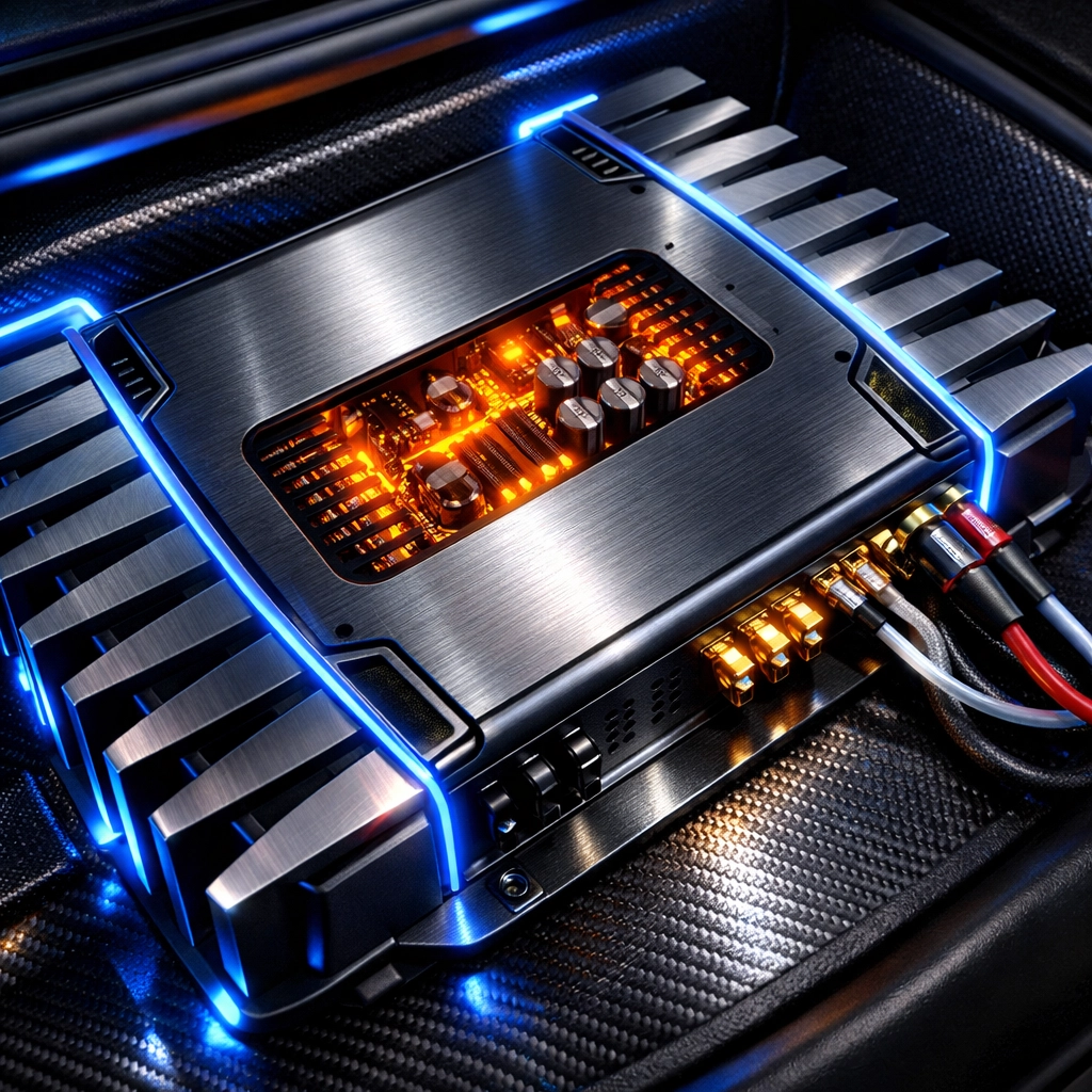
Amplifier Placement Strategy
Select a mounting location. Common areas include under front seats. Behind rear seats. Trunk floor. Trunk side panels. Ensure flat mounting surface. Verify clearance for cooling fins. Amplifiers generate heat. Air must circulate. Do not mount directly to metal vehicle body. Use a wooden mounting board. This prevents ground loops. This prevents electrical interference. Avoid locations near heater vents. Avoid locations prone to moisture.
Power Wire Installation Steps
Determine wire gauge requirements. Refer to amplifier manual. Calculate total current draw. Measure distance from battery to amplifier. Purchase appropriate length.
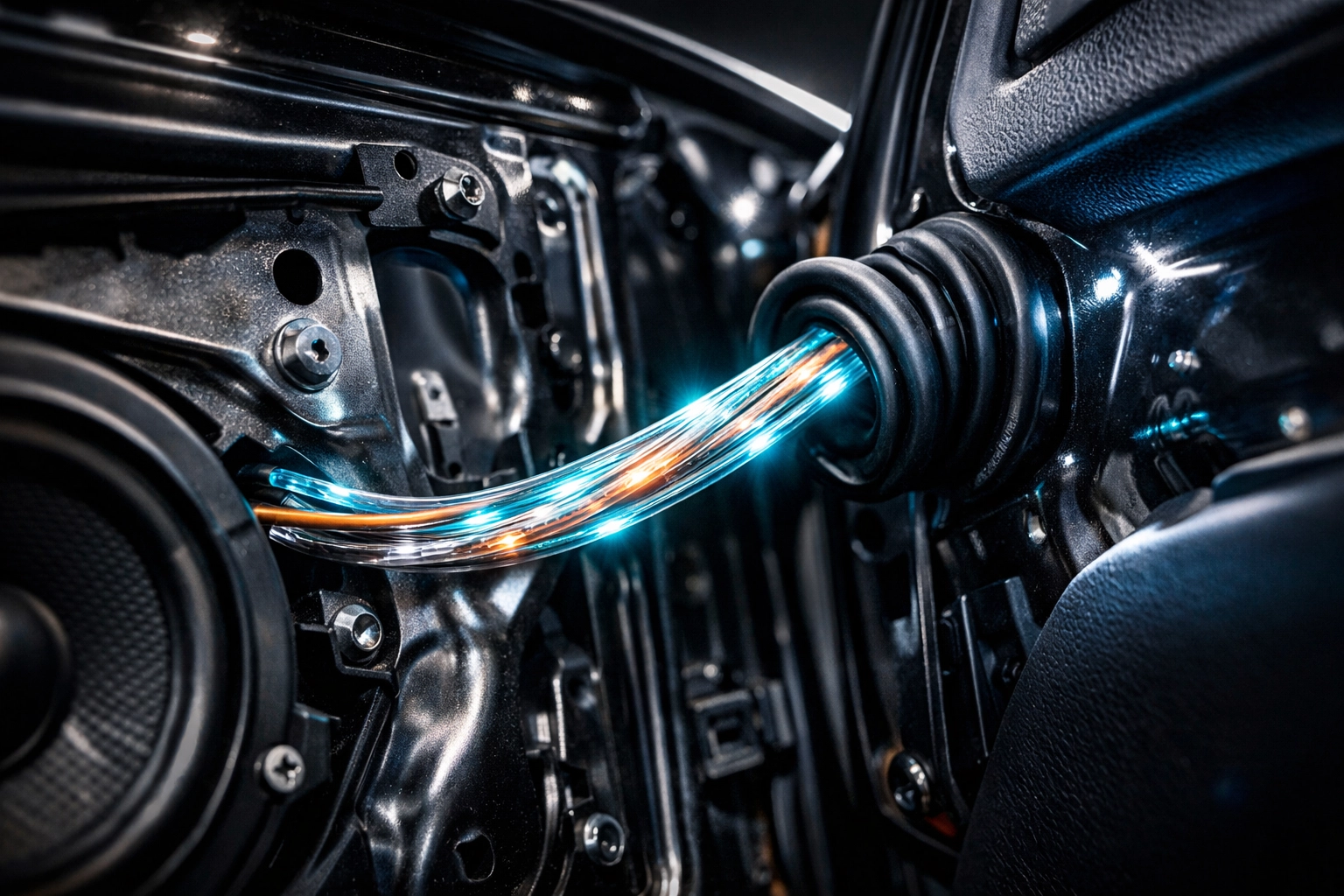
Locate firewall. Identify existing rubber grommet. Pass power wire through grommet. If no grommet exists, drill a hole. Check both sides of firewall before drilling. Avoid brake lines. Avoid fuel lines. Avoid electrical harnesses. Insert a plastic or rubber bushing into the hole. This prevents wire chafing. This prevents vehicle fires.
Route wire through vehicle interior. Remove door sill plates. Use panel removal tools. Lift carpet. Lay wire along the floor. Keep power wire away from signal cables. This prevents audible hum. This prevents engine noise in speakers.
Fuse Holder Connection
Install main fuse holder. Place holder within 18 inches of the battery. Short distance minimizes fire risk. Cut a short segment of power wire. Strip ends. Crimp ring terminal to one end. Connect to positive battery terminal. Connect other end to fuse holder input. Connect long power wire to fuse holder output. Use heat shrink tubing on all connections. Do not install fuse yet. Leave fuse out until installation is complete.
Grounding Procedures
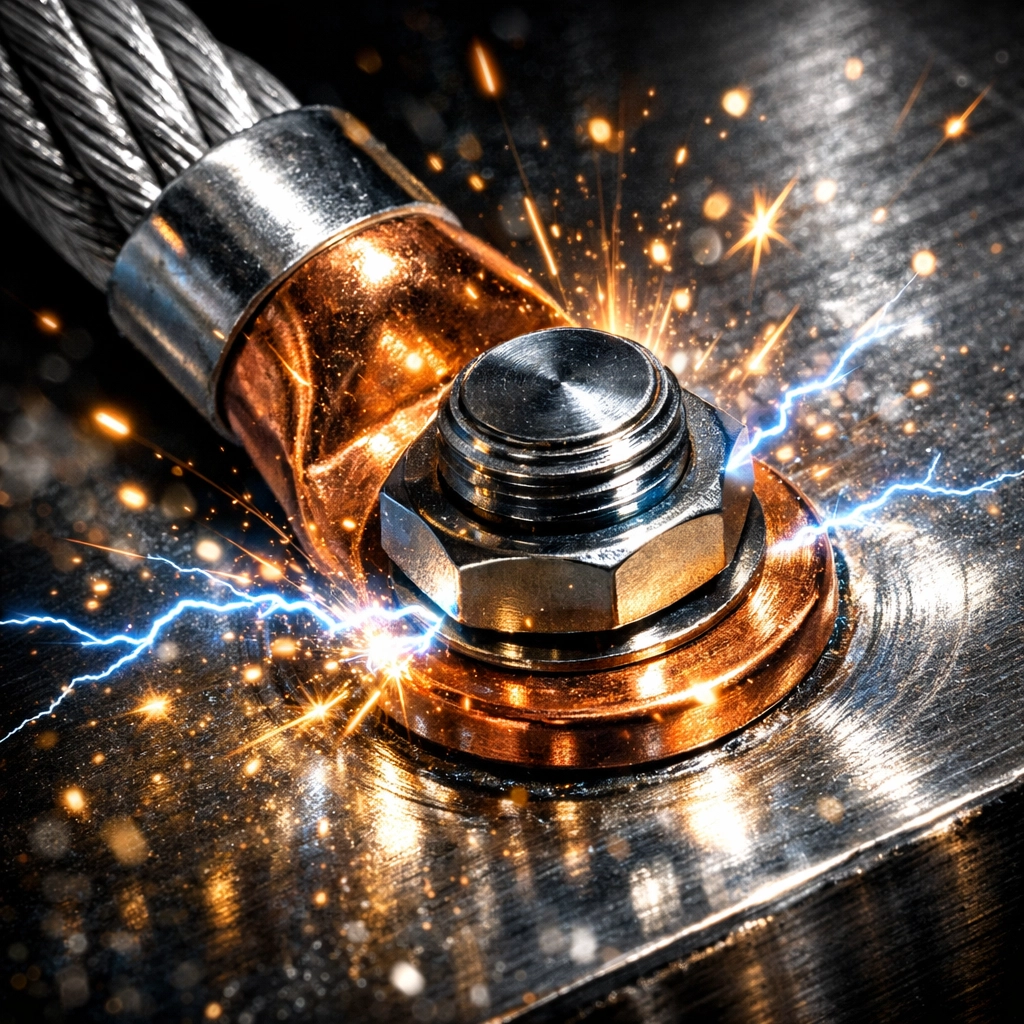
Identify ground point. Locate solid metal chassis part. Use a factory bolt if available. If drilling, check for obstructions underneath. Location must be within 18 inches of the amplifier. Short ground wires reduce resistance.
Prepare the surface. Use sandpaper. Remove paint. Remove primer. Remove rust. Expose bare metal. Metal must be shiny. Crimp ring terminal to ground wire. Bolt terminal to bare metal. Use a star washer. Tighten bolt. Ensure no movement. Apply a thin layer of grease to prevent corrosion. Connect other end to amplifier ground terminal.
Signal Cable Routing
Connect RCA cables to head unit. Pull head unit from dashboard. Plug RCAs into "Pre-out" jacks. Route cables to amplifier. Run RCAs on the opposite side of the vehicle from power wires. Cross power wires only at 90-degree angles. This maintains signal integrity. Use high-quality shielded cables.
Remote Turn-On Connection
Locate remote turn-on wire on head unit. Usually blue or blue with white stripe. This wire provides 12 volts when the radio is on. Connect remote wire using a crimp connector. Route remote wire alongside RCA cables. Connect to "REM" terminal on the amplifier. This triggers the amplifier to power up.
Speaker Wire Connections
Run speaker wires from amplifier to speakers. Use 16-gauge or 14-gauge wire. Follow factory wire paths through door boots. Avoid pinching wires in hinges. Strip wire ends. Connect to amplifier speaker terminals. Observe polarity. Positive to positive. Negative to negative. Incorrect polarity causes phase cancellation. Phase cancellation reduces bass response.
Power Distribution Components
For multiple amplifier setups, use distribution blocks. Connect main power wire to input. Run smaller wires to each amplifier. For common grounding points, use heavy-duty busbars.
Available components:
- Blue Sea 2126 Maxibus 6 x 5/16-18 Stud Common
- Blue Sea 2128 Maxibus 6 x 10-24 Screws w/ 2 x 5/16 Studs
These blocks organize wiring. They ensure secure electrical contact. They simplify troubleshooting.
Auxiliary Power Options
Some custom builds require AC power for peripheral equipment.
Available inverters:
These provide clean power for mobile workstations or specialized audio gear.
Final Assembly and Inspection
Inspect all connections. Tug on wires to ensure crimps are tight. Inspect fuse holder. Ensure no bare wires are exposed. Secure all loose wiring with wire ties. Reinstall interior panels. Replace door sills. Reinstall head unit.
Reconnect negative battery cable. Tighten terminal. Install main power fuse into the holder near the battery.
Initial Testing
Turn on vehicle ignition. Turn on head unit. Check amplifier status light. Green indicates normal operation. Red indicates protect mode. If protect mode occurs, disconnect battery and re-check ground.
Verify sound output. Check each speaker individually. Use balance and fader controls. Confirm audio is clear. Confirm no alternator whine is present.

Tuning the Amplifier
Set gain correctly. Turn head unit volume to 75%. Turn amplifier gain to minimum. Slowly increase gain until distortion is audible. Back gain off slightly. This prevents speaker damage. This maximizes signal-to-noise ratio. Gain is not a volume knob. Gain matches input sensitivity.
Adjust crossovers. Set High Pass Filter (HPF) for door speakers. Typically 80Hz. This removes low bass. This prevents distortion. Set Low Pass Filter (LPF) for subwoofers. Typically 80Hz. This removes high frequencies.
Service and Shipping
DIY Customs Store provides components for automotive enthusiasts nationwide. We ship to all 50 states. Orders over $200 qualify for free shipping. Online ordering is available at diycustoms.store.
For discounted equipment, visit our outlet clearance section. This section contains scratched, dented, and end-of-life products. Brands include Linkswell, JL Audio, and Hertz. Inventory changes frequently.

Technical Specifications Table
| Component | Function | Recommended Gauge |
|---|---|---|
| Main Power | Battery to Amp | 0 - 4 AWG |
| Ground Wire | Amp to Chassis | 0 - 4 AWG |
| Speaker Wire | Amp to Speaker | 12 - 16 AWG |
| Remote Wire | Head Unit to Amp | 18 AWG |
| RCA Cable | Signal Transfer | N/A (Shielded) |
Follow all manufacturer guidelines. Refer to vehicle service manual for specific disassembly instructions. Maintain clean workspace. Use proper safety gear. Professional installation recommended if uncomfortable with high-current electrical systems.
Keywords: amplifier installation guide, car audio, car amplifier wiring, DIY car audio, amplifier grounding, power wire routing.
Meta Description: Learn how to install a car amplifier with this technical step-by-step guide. Covers power wiring, grounding, signal routing, and tuning for optimal performance.
Excerpt: A utilitarian guide to car amplifier installation. Detailed instructions on wiring, firewall passage, grounding techniques, and system tuning for automotive DIYers.